
Roughly four out of five field callbacks on hardwired lit house numbers trace back to three preventable electrical mistakes: tying DC-only LED modules directly onto an unrectified 12V AC magnetic landscape transformer, daisy-chaining five digits in series instead of wiring a parallel manifold, or running 90 feet of thin 18/2 bell wire without checking copper voltage drop.
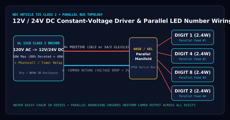
NEC Article 725 Class 2 Low-Voltage Rules Explained
Hardwired illuminated house numbers operate on NEC Article 725 Class 2 power-limited circuits, supplied by a UL 1310 or UL 879 listed constant-voltage power supply. Class 2 circuits cap output at 60W for 12V DC (5A max) and 96W–100W for 24V DC (4A max). Because shock and fire energy are intrinsically limited on the secondary side, low-voltage cable rated CL2, CL3, or direct-burial UF / Landscape Low-Voltage can pass through framing cavities to the exterior wall penetration without requiring rigid metallic conduit all the way to each individual numeral stud.
However, the 120V AC primary connection feeding the Class 2 driver must always reside inside an accessible, code-compliant junction enclosure—such as a garage utility wall, basement joist bay, attic access panel, or outdoor NEMA 3R weatherproof box—never buried blind behind finished exterior stucco or drywall.
Why 12V AC Landscape Transformers Cause 60 Hz Shimmer or Instant Failure
Existing outdoor path-lighting transformers almost always output 12V to 15V AC (alternating current), whereas precision architectural LED numbers use regulated constant-voltage 12V DC or 24V DC SMD2835 arrays. Connecting DC-only LED strips directly to raw 12V AC reverse-biases the diodes 60 times per second, causing visible camera/peripheral flicker and premature thermal breakdown.
- Dedicated Driver Best Practice: Install a dedicated regulated 12V DC or 24V DC UL Class 2 electronic driver sized so steady-state load sits between 30% and 75% of rated wattage (applying the standard 20%–25% continuous-duty derating headroom).
- Tapping an Existing 12V AC Landscape Run: Only permissible if you install an inline IP67 full-wave bridge rectifier + DC buck-boost regulator module ahead of the digits so output holds a rock-steady 12.0V DC regardless of transformer tap sag.
12V DC vs. 24V DC Copper Voltage-Drop Physics
For an identical total wattage—say five 8-inch halo digits drawing 2.4W each, or 12.0W total—doubling system voltage from 12V DC to 24V DC cuts current in half (from 1.00 A down to 0.50 A) AND doubles the allowable voltage drop for the same percentage loss, extending maximum wire run distance by 4× on the exact same copper gauge!
| CL2 / Landscape Wire Gauge | Loop Resistance (per 100 ft two-way) | Max Run @ 12V DC (12W Load, <3% Drop) | Max Run @ 24V DC (12W Load, <3% Drop) | Typical Residential Use Case |
|---|---|---|---|---|
| 18/2 AWG Stranded Cu | 1.28 Ω | 28 ft | 112 ft | Garage driver mounted directly behind entry wall (<25 ft) |
| 16/2 AWG Stranded Cu | 0.80 Ω | 45 ft | 180 ft | Standard basement/utility closet to front porch soffit |
| 14/2 AWG Direct-Burial | 0.51 Ω | 70 ft | 280 ft | Detached driveway column or front courtyard masonry wall |
| 12/2 AWG Direct-Burial | 0.32 Ω | 112 ft | 445 ft | Long estate gate pillars & monument walls up to 400+ ft |
Parallel Manifold Wiring vs. Daisy-Chain Sag
Every individual illuminated digit ships with an 18-inch to 36-inch twin-lead pigtail exiting through a rear hollow threaded standoff or center wire boss. Never wire constant-voltage LED digits in series, and avoid daisy-chaining thin 22 AWG internal jumpers through five digits in a row—by the fifth digit, trace resistance drops terminal voltage enough to shift brightness by 15%–20%.
V+) leads together and all negative (V-) leads together using lever-nut connectors (such as Wago 221-415) inside dielectric silicone gel-filled enclosures for damp masonry cavities. Every digit receives identical voltage within 0.02V.Step-by-Step Pre-Closeout Multimeter Checklist
- Unloaded Polarity Check: Before connecting LED leads, power the Class 2 driver and verify exact DC voltage (
12.0V–12.2V DCor24.0V–24.2V DC) and red/black polarity at the facade splice point. - Loaded Terminal Drop Check: Connect all digits in parallel and measure DC voltage under load; ensure at least
11.6V DC(on 12V systems) or23.2V DC(on 24V systems) reaches the splice manifold. - Drip Loop & Neutral-Cure Seal: Form a downward drip loop inside wall framing and seal exterior wire penetrations exclusively with neutral-cure (oxime/alkoxy) 100% silicone—never acetic-acid vinegar-smelling silicone, whose vapors corrode copper solder pads and brass standoffs.
Test your exact cable footage, digit count, and voltage in our Low-Voltage Voltage-Drop & Transformer Console to generate a ready-to-print electrician specification sheet.
Need Driver Sizing or a Custom Halo Number Quote?
Preview your exact digits in our Live Kelvin & Standoff Halo Studio or send your cable distance and facade details to info@litnumbers.com.